


Crosstalk between cables . and radiated emission from cables to antennas with the focus on vehicle applications has been investigated. In particular, the effect of using lightweight materials instead of metal in the vehicle chassis has been studied. Computer simulations of this were done in CST, and in the conclusion cable placement depending on material selection is discussed.
Cables carrying time-varying electric currents will give rise to unwanted electromagnetic (EM) radiation that will couple to other cables, humans, and antennas nearby. The radiation can be reduced by shielding the cables, but since shielded cables are more expensive and heavier than unshielded cables they are not really a realistic choice for vehicle manufacturers. An alternative method is to place cables directly on a ground plane, such as a metal chassis, since this will lead to reduced radiation.
Electrical vehicles demand large electric currents from the battery to the motor. Also, these vehicles may be constructed of lightweight materials (such as plastics, carbon fiber, etc), and this may further increase the unwanted radiation, since the shielding effect of the chassis is reduced.
This motivates a special investigation of the EM fields for these types of vehicles so that the cable choice and routing can be chosen to reduce the unwanted radiation to an acceptable level.
In the present paper we use CST Microwave Studio [1], a commercial software package based on the finite integration technique (FIT), to compute radiated electric fields from cables in the frequency range 5 MHz to 1 GHz.
Numerical Simulations
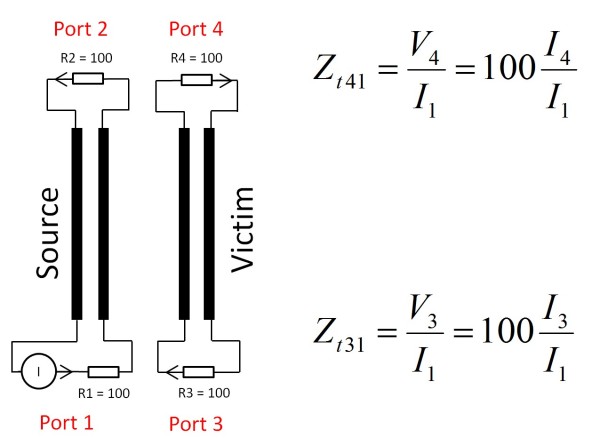
First we consider crosstalk. Two pairs of wires are placed 10 mm over a sheet as shown in Figure 1. The left pair of wires is the source wire with its return wire. The source wires are excited with a current generator with the amplitude 1 A. The wires to the right represent the victim cable. Here we will get induced currents due to (undesired) over-the-air coupling. Each wire pair is terminated with 100 ohm resistors in both ends. The terminations are illustrated in Figure 2. We define transfer impedances that will have simple relations to the induced currents, these expressions are also shown in Figure 2.
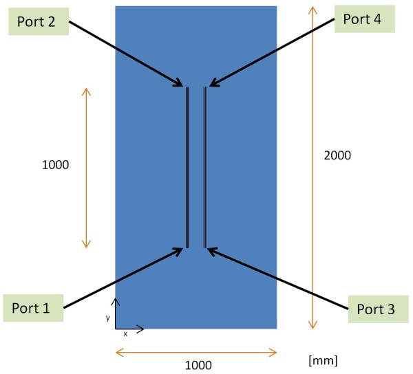
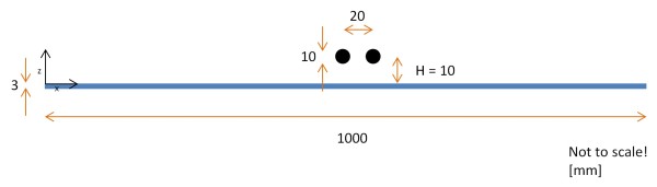
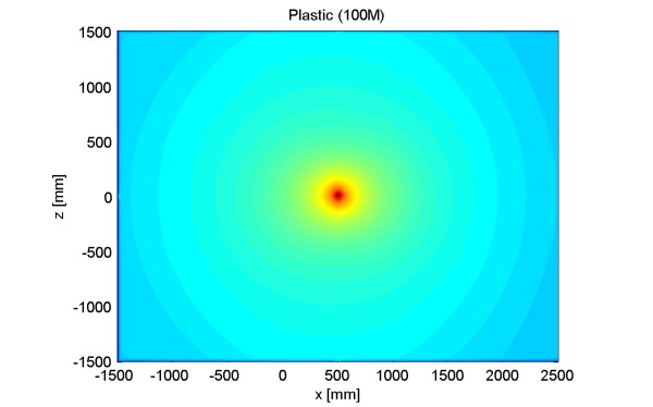
Next, we consider the radiated fields. For this case we have removed the victim cable and placed the source cable in the center above the sheet. A cross-section of this geometry is shown in Figure 3.
![Figure 4 – Crosstalk in terms of transfer impedance in logarithmic scale [dBohm]. The frequency range is from 5 MHz to 1 GHz. The blue curve is the excitation signal (EXC) at 40 dBohm. The green curves are the near end cross talk (NEXT) and the red curves are the far end cross-talk (FEXT). Solid lines indicate that the sheet is electrically conducting (PEC and steel) and dashed lines indicate that the sheet is not conducting (plastic and vacuum).](https://www.electronic.se/wp-content/uploads/2015/01/Fig4-transf_impedance-600x421.jpg)
Results
The near end crosstalk (NEXT) and far end crosstalk (FEXT) are shown in Figure 4 for the various materials of the sheets. We see that the material of the sheet will influence the transfer impedance. Non-conducting materials (plastic and vacuum) will increase the coupling with around 20 dB compared to electric conducting materials (PEC and steel), for the studied geometry.
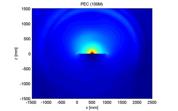
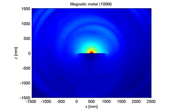
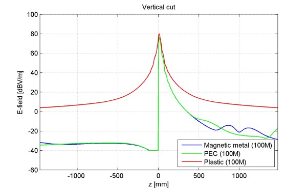
The electric field in the cross section (from Figure 3) is shown in Figure 5, 6, and 7 for a sheet made of perfect electric conductor (PEC), steel, and plastic, respectively. It is obvious from these figures that the electric field is reduced by a conducting sheet, especially below the sheet but also substantially above the sheet. In Figure 8 a vertical cut has been selected in the previous figures to illustrate this. It is clear that conducting material reduces the electric field and that PEC and steel behave approximately in the same way. The increase of electric field strength is around 24 dB one meter above the sheet if the sheet is made of plastic instead of metal. All curves show a 1/R-decay of the field amplitude for large distances, were R is the distance from the sheet (in Figure 8 R is equal to z). This is in agreement with theory.
Conclusions
A vehicle chassis made of electric conducting materials will act as a shield that reduces the electromagnetic fields from cables. When constructing vehicles using non-conducting materials, this must be taken into account and cable shielding may have to be introduced. Cable routing close to metals should be made if possible.
Ulf Carlberg, Peter Ankarson, Christer Karlsson, Jan Carlsson SP Sveriges Tekniska Forskningsinstitut
References
[1] CST Microwave Studio http://www.cst.com/Content/Products/