


Abstract . The possible threat of a high-power microwave (HPM) weapon that destroys electronic equipment or its function is today taken seriously, and test methods and test standards are slowly adapted to this situation. However, a complete standard methodology for destructive HPM testing of complex electronic systems does not exist. In this article, the current status of relevant standards is reviewed, and FOIs ongoing work to contribute to the development of an up-to-date standard is mentioned.
Index Terms— High-Power Microwave (HPM), High-Power Electromagnetic (HPEM) Environment, Standards, Destructive Testing, Test Methodology, Reverberation Chamber, Vircator
Introduction
The progress in technologies pertinent to the generation of directed-energy weapons based on non-nuclear high-power electromagnetic pulses [1][2] has reached a sufficient maturity for allowing a development of high-power microwave (HPM) weapons and for taking the step from the laboratory into the operative arena [3][4] where the objective of the HPM weapon is to intentionally destroy electronic equipment or its function.
The HPM threat is acknowledged in official government reports (e.g. [5]) and compilations of hundreds of radiation sources exist [6][7]. Furthermore, HPM weapons are also mentioned as being explored to be a part of U.S. offset strategy for their global military power projection capability [8].
During the last decade there has been an increasing use of complex and networked electronics for all kinds of military applications, as for example in command, control, communications, computers, and intelligence (C4I) systems, weapons systems and even in ammunition. This trend is expected to continue to escalate in the near future.
As a consequence, military missions become more and more dependent on operational reliability of electronic systems and therefore increasingly vulnerable to electromagnetic attacks (EA) in general, and HPM weapons in particular [9]. Qualification testing of military equipment with respect to this kind of intentional electromagnetic interference (IEMI) will be an important step in protecting one’s own electronic systems.
The high-power electromagnetic (HPEM) environment caused by HPM weapons has been introduced in standards and some test methods have been outlined. However, a complete standard methodology for HPM susceptibility tests on complex electronic systems does not exist. In this article, we present issues with high-power destructive HPM susceptibility tests, summarize relevant standards and outline a test methodology.
Issues with HPEM Destructive Testing
Four issues that have to be considered in HPEM destructive testing have been identified:
- Susceptibility testing is heavily time consuming if results are to be statistically relevant.
- Destructive tests involve the destruction of many test objects – which may be costly.
- Destructive tests are in the regime of non-linear irreversible effects.
- In an electronic device or system, different individual components might be affected when varying the frequency or the angle of incidence.
These four issues are elaborated upon in this section.
To fully determine the electromagnetic susceptibility of a device, it is required to illuminate the device under test (DUT) from many different directions, especially if the DUT is large in relation to the wavelength [10], at every frequency using at least two polarizations.
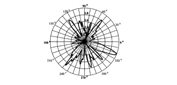
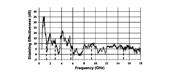
Figures 1 and 2 illustrate the importance of high resolution in both direction and frequency measurements.
Figure 1 shows the results of a radiation susceptibility test in an anechoic chamber using 120 angles and two polarizations [11]. The test took 48 hours. The figure clearly shows that a slight change in angle of incidence can give a large change in the electromagnetic coupling into the object.
Figure 2 shows the measured shielding effectiveness of a device [12] As seen in the figure, a slight shift in frequency can give a large difference in shielding effectiveness. Thus, a test matrix that covers all directions as well as every frequency in a relevant frequency band will be very costly both in time and in test objects. Hence, a more efficient, but still relevant, test method is required.
As an HPM weapon aims at achieving destructive effects, the system response will be non-linear and scaling from low-level coupling measurements or disturbance tests will not be possible. It follows that testing must be performed in the destructive non-linear regime. It should be noted that destructive HPM effects may be due to several different physical mechanisms, mainly related to either the absorbed electric energy or to the electric field strength [13][14][15].
For example, overvoltages can lead to a high-voltage dielectric breakdown or to surface inversion due to mobile ion contaminants. An electric breakdown can result in a current surge evaporating material. Induced voltages of the same order as the circuit operating voltage may lead to a temporary upset (non-destructive) [2]. Bursts of HPM pulses can result in cumulative effects eventually breaking a component. To find out exactly which mechanism is responsible for a particular equipment failure event can be challenging. It is usually not relevant from a practical point of view which destructive mechanism is achieved, but this has to be considered in HPM susceptibility testing.
Another issue is component testing versus system testing. The Tasca curve can be expressed as the energy density required to destroy an integrated circuit as a function of the pulse length [15]. If the same component of a DUT is destroyed during a test series, the Tasca curve for the system will be related to the Tasca curve of that particular component. But if different components are destroyed at different illumination parameters, the Tasca curve of the system would be related to the envelope of the Tasca curves of different components.
Standards – HPEM Environment
During the last decade several standards have emerged with descriptions of the HPEM environment relevant for the IEMI threat from HPM.
IEC 61000-2-13
The International Electrotechnical Commission (IEC) in 2005 published the IEC 61000-2-13 standard with definitions of a ”set of typical radiated and conducted HPEM environment waveforms that may be encountered in civil facilities” [16]. In this document high-power conditions are considered to exist if the peak electric field exceeds 100 V/m. Both single pulse radiation and bursts of pulses are considered as threats. Examples of typical HPEM waveforms in the time and frequency domains as well as some examples of HPEM generators are given in annexes.
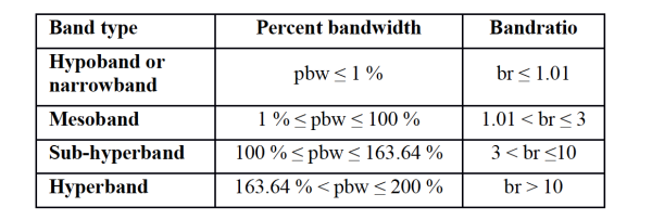
The classification of HPEM sources in IEC 61000-2-13 is based on the spectral bandwidth. To include as many different HPEM sources as possible, it is recommended to select the low and high frequency limits (fl and fh) of emitted radiation pulses such that 90 % of the total pulse energy is contained within these limits. The standard gives a classification of HPEM sources based on bandwidth as given in Table 1, where the percent bandwidth, pbw, is defined as pwb = 100·2(fh–fl)/(fh+fl) and the bandratio, br, as br = fh/fl.
MIL-STD-464C
MIL-STD-464C from 2010 ”establishes electromagnetic environmental effects interface requirements and verification criteria for airborne, sea, space, and ground systems” [17]. It cites other standards and documents, including them in the requirements. MIL-STD-464C recognizes subsystem and equipment electromagnetic interference, electrostatic charge, and multipaction as well as external RF electromagnetic environments, lightning, and HPM as potential sources of interference.
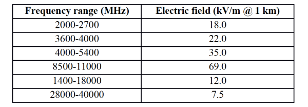
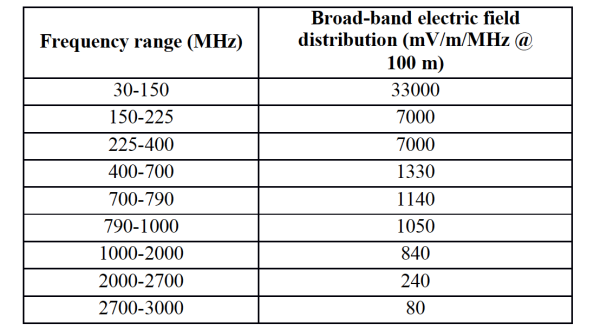
External electromagnetic environments are defined and tabulated as electric field levels as function of frequency, while requirements are specified per type of platform. The MIL-STD-464C defines HPM as a radio frequency environment produced by sources capable of emitting microwave radiation with high power and high energy density, nominally with peak power over 100 MW, with operating frequency typically between 100 MHz and 35 GHz, in single pulses, repetitive pulses, pulses of more complex modulation, or continuous wave emissions.
The standard differentiates between narrowband (pbw < 1 %) and wideband (pbw > 1 %) HPM sources, based on the underlying technology (electron beam diode or similar, and fast switching techniques and impulse generators, respectively). The definition of the HPM electromagnetic environment given in MIL-STD-464C is summarized in Tables 2 and 3. The electric field strength is here given at a distance of 1 km and 100 m, respectively, and is used in examples of calculation of standoff distances for some typical military situations.
NATO AECTP 250
The NATO defence standard AECTP 250 2nd ed. presents ”characteristics and sources for electrical and electromagnetic conditions that influence the design and operation of defence materiel” including RF environments, electrostatic phenomena, atmospheric electricity and lightning, DC and LF fields, nuclear EMP, electrical power quality, etc. Leaflet 257 [18], treats HPM as a relatively new research area, adapting the schematic comparison of the spectral density distribution for lightning EMP, nuclear EMP and different types of HPM sources from IEC 61000-2-13. AECTP 250 defines the HPM frequency range as in MIL-STD-464C and classifies HPM sources into four briefly described types coupled to possible scenarios:
- Mobile/platform sources targeting infrastructure facilities from a distance
- Portable sources carried into or close to a target
- Conducted sources directly injecting energy into conductors
- Projectile-based sources irradiating an entire facility
It is recognized that the scenario details depend on a number of variables, as infrastructure topology, purpose of attack, etc. In AECTP 250, four HPM waveforms are specified: continuous wave (CW), pulsed narrowband (NB), damped sinusoid (DS), and ultra-wideband (UWB). The available power of CW sources is stated to vary from kW to tens of MW, while pulsed sources go to hundreds of MW or higher.
ITU-T K.81
The recommendation ITU-T K.81 [19], issued by the International Telecommunication Union, contains ”guidance on establishing the threat level presented by intentional HPEM attack and the physical security measures that may be used to minimize this threat”.
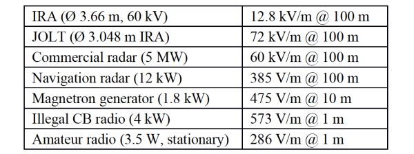
The HPEM sources considered are those from IEC 61000-2-13 augmented by additional recent sources. The recommendation introduces an elaborate classification into threat portability levels, threat availability levels, intrusion areas, target vulnerability and immunity levels, etc. and tabulates several examples of HPEM threats and gives examples of required mitigation EM levels. The HPEM threats considered in ITU-T K.81 include impulse radiating antenna, commercial radar, navigation radar, magnetron generator, illegal citizen band (CB) radio, amateur radio, stun gun, lightning surge generator, CW generator, and commercial power supply.
Calculated examples of peak electric field strength are given with respect to portability levels and intrusion areas (possible target distance); compiled in Table 4. Except for the first two sources, these are commercially or otherwise available sources for insurgents etc., but ITU-T K.81 does not embrace high-power narrowband HPM sources being developed for military purposes.
Standards – HPEM Test Methods
Several standards concerning conventional EMC testing are relevant for HPM/HPEM susceptibility testing, and some of the most pertinent are cited below.
IEC/TS 61000-5-9
The IEC/TS 61000-5-9 [20], discusses methods for the assessment of system-level susceptibility, typically vehicles, aircraft and ships, to HPEM and HEMP (nuclear high-altitude electromagnetic pulse) threats. The standard emphasizes the importance to generate functional and topological descriptions of the system and subsystems before actual testing, i.e. the intentional flow of information in the system and the relative locations of physical units together with their physical interconnections.
This is relevant for understanding front-door and back-door coupling paths, which together with the physical dimensions of components and cables can indicate possible weaknesses of the system as well as hints to possible protection measures. System analysis is used to identify critical subsystems and equipment and to select test points with possible high stress levels and function criticality. Actual testing can be performed on the entire system or, if this is too large, on subsystems. Low-level testing can be scaled to threat levels, but does not include non-linear effects such as arcing. High-level tests can consist of current injection into cables or surfaces, of high-level illumination with typical NB, DS or UWB pulsed HPM sources, or of reverberation chamber tests.
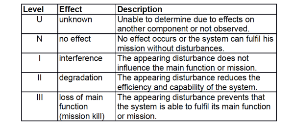
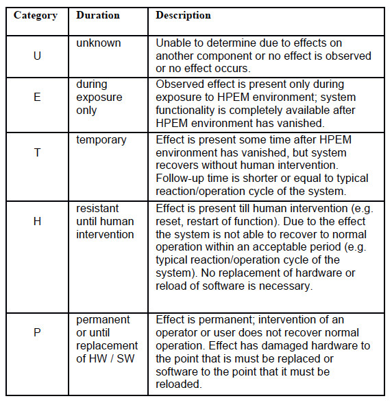
The experimentally determined susceptibility/immunity results often need to be adjusted with a safety margin due to uncertainties in the test method and system configuration before comparison with a set of HPEM threats. Furthermore, the susceptibility/immunity has to be qualified by classification of the effect by operational criticality and duration. These classifications, as given in IEC/TS 61000-5-9, are reproduced in Table 5 and Table 6. The classifications are then combined in a matrix to characterize the effects obtained in testing. High-level HPEM test techniques are discussed in annex H of IEC/TS 61000-5-9.
Plane-wave irradiation, as in anechoic chambers or TEM-cells, may present an environment more similar to the actual threat situation, but require an enormous number of tests to be performed at every frequency, angle of incidence and polarization. Reverberation chambers offer a statistically isotropic environment where all coupling paths are excited simultaneously which simplifies testing, but require test levels higher than the expected threat level and cannot represent all threat pulse shapes, in particular very short pulses.
IEC 61000-4-21
Reverberation chamber test methods are described in more detail in the international standard IEC 61000-4-21 [21] . This standard provides comprehensive descriptions of reverberation chamber statistical techniques, test setups, validation methods, and guides for performing radiated immunity, radiated emission, shielding effectiveness, and antenna efficiency measurements.
RTCA DO-160G and DO-357
The RTCA standard DO-160G [22], section 20, on radio frequency susceptibility (radiated and conducted) describes test procedures for injected signals from 10 kHz to 400 MHz and radiated fields between 100 MHz and 18 GHz. The purpose is to ”determine whether airborne equipment will operate within performance specifications when the equipment and its interconnecting wiring are exposed to a level of RF modulated power”.
Equipment is categorized in thirteen categories and tested according to which electric field strengths it should withstand in operation. The standard specifies how to arrange the equipment under test (EUT) electrical bonding, grounding, length and placement of interconnecting cables, antenna orientation and positioning, shielding of enclosure, test frequency spacing, and test report contents. Two radiated susceptibility test procedures are specified in DO-160G, including field calibration, test set-up, and signal modulations to be used.
The first procedure is using directional irradiation with calibrated fields in an anechoic chamber, and the second utilizes reverberation chamber measurements. For the reverberation chamber method, field uniformity validation, chamber and receive antenna calibration, maximum chamber loading, Q factor and time constant calibration, etc. are described together with formulas for calculation of statistical quantities.
A user guide with more detailed specifications and procedures for conducting the radiated and conducted tests described in DO-160G is given in DO-357 [23].
MIL-STD-461F
The MIL-STD-461F [24] provides interface and associated verification requirements for control of EMI emission and susceptibility characteristics of electronic, electrical, and electromechanical equipment and subsystems.
Section 5.20 contains requirements for radiated susceptibility with electric fields between 2 MHz and 40 GHz. Limit electric field levels are specified per type of military platform (aircrafts, ships, submarines, ground, and space) and frequency range.
Above 30 MHz, requirements must be met for horizontal and vertical polarization, while testing using circular polarization is not acceptable.
Two alternative test procedures are described in MIL-STD-461F: direct EUT irradiation within a shielded enclosure (2 MHz – 40 GHz) and reverberation chamber measurements (200 MHz – 40 GHz). For both, the standard defines test setup with equipment configuration and distances, procedures for calibration of antennas and probes, procedures for EUT testing, as well as data presentation guidelines.
Status of Standards
Since the descriptions of the HPEM environment for HPM are based on compilations of data on laboratory HPM sources and commercial radiation sources of lesser peak power, there is some uncertainty regarding which power levels that actually will constitute a real-world HPM threat to electronic equipment. Some standards identify threat situations with specific equipment and distance, which is relevant from a practical point of view, but for the development of test methodology idealized situations must be used and tests be conducted with specific threat pulses.
Some standards (as IEC 61000-2-13 and MIL-STD-464C) focus attention on the HPEM susceptibility as function of frequency and present limits of the electric field for different frequency intervals without regarding other properties of the HPM pulse. This is an important step but does not fully acknowledge the variation in pulse shapes generated by different threat sources. At least the following parameters of pulsed microwave radiation should be considered in the development of a testing methodology for equipment:
- Electric field strength (peak & temporal profile)
- Pulse duration
- Total pulse energy
- Frequency content
- Angle of incidence
- Polarization
The susceptibility of typical electronic devices varies with frequency, but also the frequency content within the pulse as a function of time as well as the energy content at each frequency may be important for achieving effects.
Frequency content, angle of incidence, and polarization determine the effectiveness of radiation coupling into wires and components in the target, while pulse energy, pulse duration, and electric field variation in the pulse (at a fixed coupling) are related to energy and power dissipation into components. This distinction makes it natural to implement a stepwise process for HPM testing: first determine the frequency for which a specific DUT is most susceptible; second investigate the susceptibility as a function of angle of incidence and polarization.
Different HPEM test methods have different advantages. Reverberation chamber testing, e.g. as described in IEC 61000-4-21, is efficient in determining an averaged susceptibility as function of frequency only, but gives no information on the susceptibility as function of polarization, angle of incidence or pulse profile.
Directional irradiation can provide information on the dependence of the susceptibility on the latter parameters, but requires extensive testing to reach an acceptable level of confidence. Since HPEM effects on particular equipment can vary, a classification scheme is needed. As elaborated in IEC/TS 61000-5-9, effects of different criticality and duration can occur in HPEM exposure. The destructive HPM testing discussed here would according to Table 5 and Table 6 be described as IIIP.
Although there exists standards defining HPM environment and standards for HPM susceptibility testing of equipment, a comprehensive and more general test methodology needs to be defined. The non-linear HPEM susceptibility of equipment to destructive HPM pulses needs further characterization and development of test methodology. To contribute to the development of a standard for a test methodology for destructive HPM testing, FOI is elaborating on a test method that consists of the following two test phases:
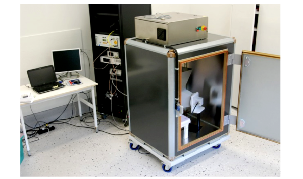
- First, the DUT is tested in a reverberation chamber (RC) where the minimum power density required to destroy the DUT is established and at which frequency this occur.
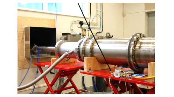
- Second, the DUT is tested for its most sensitive direction of attack and polarization using a frequency-tuned HPM generator or a GTEM cell.
To realize this test method, designated equipment for both test steps must be in place. FOI has established a facility for destructive HPM testing based on an RC for identification of susceptible frequency, lowest electric field strength and pulse length required (Figure 3), and an HPM generator (vircator) for determination of susceptibility as function of angle of incidence, polarization, pulse energy and electric field strength (Figure 4) [25][26][27].
Conclusion
The IEMI threat from HPM weapons is emerging and relevant test standards are not fully up-to-date concerning this threat. FOI is dedicated to contribute to the development of standardization of a relevant method of destructive HPM testing.
Anders Larsson, Sten E Nyholm and Tomas Hurtig
FOI – Swedish Defence Research Agency
Norra Sorunda, Sweden
References
- D. V. Giri, High-power electromagnetic radiators, Cambridge: Harward University Press (2004).
- J. Benford, J. Swegle and E. Schamiloglu, High power microwaves, 2nd ed., New York: Taylor & Francis (2007)
- M. Gunzinger and Ch. Dougherty, “Changing the game: The promise of directed-energy weapons”, Center for Strategic and Budgetary Assessments, USA (2012).
- R. Jackson, “CHAMP – lights out”, http://www.boeing.com/Features/2012/10/bds_champ _10_22_12.html (retrived 31 January 2014).
- Houce of Commons Defence Committee, ”Developing threats: electro-magnetic pulses (EMP)” Report No HC 1552, House of Commons, London: The Stationery Office Limited, February 2014
- R. Hoad, C. Harper and N. Jenner, ”Infrastructure assessment and protection from RFDEW and IEMI environments”, presentation at the Directed Energy Systems 2013, London, United Kingdom, 6-7 March 2013.
- N. Mora, F. Vega, G. Lugrin, F. Rachidi and M. Rubinstein, “Study and classification of potential IEMI sources”, Summa Notes SDAN 41 (2014).
- R. Martinage, “Toward a new offset strategy. Exploiting U.S. long-term advantages to restore U.S. global power projection capability”, Center for Strategic and Budgetary Assessments, USA (2014).
- M. Suhrke, “The threat of high power microwaves to infrastructure” presentation at the Directed Energy Systems 2013, London, United Kingdom, 6-7 March 2013.
- P. F. Wilson, “Advances in Radiated EMC Measurment Techniques”, Radio Science Bulletin, No 311, December 2004, pp. 65-78.
- M. Höijer, M. Bäckström and J. Lorén, “Angular patterns in low level coupling measurements and in high level radiated susceptibility testing”, in Proc. Int. Zurich Symp. Tech. Exhibition Electromagnetic Compatibility, Zürich, Switzerland, 18-20 August 2003.
- M. Bäckström, K.G. Lövstrand, 2004, Susceptibility of electronic systems to high power microwaves: Summary of test experiences, IEEE Transactions on Electromagnetic Compatibility, Vol. 46, No. 3, August 2004, pp. 396 – 403.
- J.H. Yee, W.J. Orvis, G.H. Khanaka, D.L: Lair, ”Failure and Switching Mechanisms in Semiconductor P-N Junction devices”, IEEE Power Electronics Specialists Conference, Albuquerque, NM, USA, 6 Jun 1983, pp. 154 – 159.
- R. Blish, N. Durrant, ”Semiconductor Device Reliability Failure Models”, International SEMATECH, Technology Transfer #00053955A-XFR, 2000.
- D. M. Tasca, ”Pulse Power Failure Modes in Semiconductors”, IEEE Transactions on Nuclear Science, vol. 17, pp. 364-372, 1970.
- ”Electromagnetic Compatibility (EMC) – Part 2-13: Environment – High-power electromagnetic (HPEM) environments – Radiated and conducted”, IEC 61000-2-13, 1st edition, International Electrotechnical Commission, March 2005.
- ”Electromagnetic environmental effects requirements for systems”, MIL-STD-464C, Department of Defense Interface Standard, 1 December 2010.
- ”Electrical and electromagnetic environmental conditions”, AECTP 250, edition 2, Leaflet 257 ”HPM”, NATO standardization agency, January 2011.
- ”High-power electromagnetic immunity guide for telecommunication systems”, Recommendation ITU-T K.81, International Telecommunication Union, August 2014.
- ”Electromagnetic Compatibility (EMC) – Part 5-9: Installation and mitigation guidelines – System-level susceptibility assessmants for HEMP and HPEM”, IEC/TS 61000-5-9, Edition 1.0, International Electrotechnical Commission, July 2009.
- ”Electromagnetic Compatibility (EMC) – Part 4-21: Testing and measurement techniques – reverberation chamber test methods”, IEC 61000-4-21, Edition 2.0, International Electrotechnical Commission, January 2011.
- ”Environmental conditions and test procedures for airborne equipment”, RTCA/DO-160G, Radio Technical Commission for Aeronautics, 8 December 2010.
- ”User Guide Supplement to DO-160G”, RTCA/DO-357, Radio Technical Commission for Aeronautics, 16 December 2014.
- ”Requirements for the control of electromagnetic interference characteristics of subsystems and equipment”, MIL-STD-461F, Department of Defense Interface Standard, 10 December 2007.
- T. Hurtig, M. Akyuz, M. Elfsberg, A. Larsson and S. E. Nyholm, ”Methodology and equipment for destructive high-power microwave testing”, EMC Europe 2014, Gothenburg, Sweden (2014).
- T. Hurtig, L. Adelöw, M. Akyuz, M. Elfsberg, A. Larsson and S. E. Nyholm, ”Methodology for destructive HPM testing”, Electronic Environment, #1.2015, pp 22-27 (2015).
- T. Hurtig, L. Adelöw, M. Akyuz, M. Elfsberg, A. Larsson and S. E. Nyholm, ”Destructive high-power microwave testing of simple electronic circuit in reverberation chamber”, EMC Europe 2015, Dresden, Germany, 16-22 August 2015.